Strength design of rotor punching plate of high speed motor
Preface:
The main drive motor of the electric drive system of new energy vehicles is developing in the direction of high power density, high torque density, high efficiency, low cost, low loss, lightweight, miniaturization, integration, and serialization. This puts forward new problems and challenges one after another to major parts suppliers.
In order to reduce the structural size, weight, and raw material cost, as well as to improve the power density and torque density, the limit speed of the drive motor rotor of new energy vehicles has gradually increased from 5000rpm ~ 8000rpm a few years ago to 12000rpm ~ 17000rpm. Some products have achieved 20000 rpm or even higher performance in the laboratory. High speed has many advantages, but it also puts forward higher and higher requirements for the structural strength design of stamping.
Due to the main drive motor of new energy vehicles, most suppliers adopt the design of a built-in permanent magnet synchronous motor, namely a permanent magnet synchronous motor (PMSM). Taking a permanent magnet motor model in the official case of ANSYS software as an example, this paper shares some common problems and solutions in the design of punching strength.
Since the centrifugal force is the square of the linear velocity, the centrifugal force of the punching plate has increased seven times in more than ten years. We know that every ten of percent increase in the performance of mechanical products is huge progress. If we want to improve the performance several times, we must need unconventional methods and efforts.
Taking the structural statics and dynamics analysis module in ANSYS Workbench # environment as an example, this paper mainly discusses the following contents in the rotor punching strength design of the built-in permanent magnet synchronous motor:
1. The calculation method considers the centrifugal force at high speed;
2. The calculation method considering the internal stress of interference fit between the rotor shaft and punching plate;
3. The calculation method of centrifugal force and interference fit is considered at the same time;
4. The influence of centrifugal force and interference fit internal stress of rotor punching plate on modal frequency;
5. Under the condition of rotor burst speed, the calculation method considers plastic materials;
6. Calculation method of ultimate failure torque and maximum press-fitting force at the interference fit between rotor punching plate and shaft;
7. Between the magnetic steel and the magnetic steel hole of the rotor punching plate, the setting of different connection relationships will affect the stress of the opposite plate;
8. The influence of grid density and quality on sheet stress;
9. Weight reduction hole, stress relief groove, geometric transition design, etc., to the influence of sheet stress;
10. The effect of magnetic steel temperature on the stress of the counter sheet;
11. The change of the shaft diameter and the influence of the internal stress of the interference fit and the stress of the counter plate;
12. The influence of electromagnetic pulse force on rotor stress;
13. Evaluation method of shear stress at the connection between rotor punching plate and rotating shaft flat key;
14. The method of saving calculation through substructure technology;
15. The calculation method of quickly adjusting the local structure depends on the sub-model technology;
16. The processing method of reconstructing the finite element model after stress deformation into the geometric model;
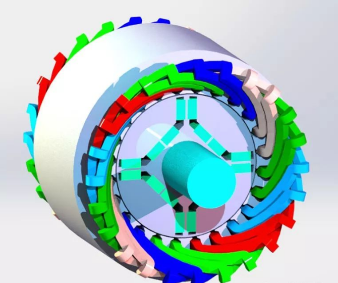
The main analysis model used in this paper comes from the official case of ANSYS software, as shown in the figure below. Some cases will also be demonstrated with other models.

The calculation method considers centrifugal force at a high speed.
Main skill points in this section:
1. With the help of three-dimensional mechanical design software solid works, a sheet geometric model suitable for simulation is established;
2. The static analysis module of the workbench environment is used to load the speed load and carry out the static strength simulation.
Centrifugal force is the main form of external load on the rotor punching plate of a high-speed motor. In this section, the static analysis module is used for demonstration and calculation by loading inertial load.
Since the centrifugal force is radial force, the axial length of the rotor basically does not affect the results, which can be calculated by the 2D plane model or flake 3D model. The latter is adopted in this paper, which can appropriately save the amount of calculation.
Another reason for using a 3D model is that it is inconvenient to load the internal stress effect caused by the interference fit between the rotor and the punching plate through the plane model. In order to facilitate the subsequent case demonstration, it is more convenient to directly establish a 3D model.
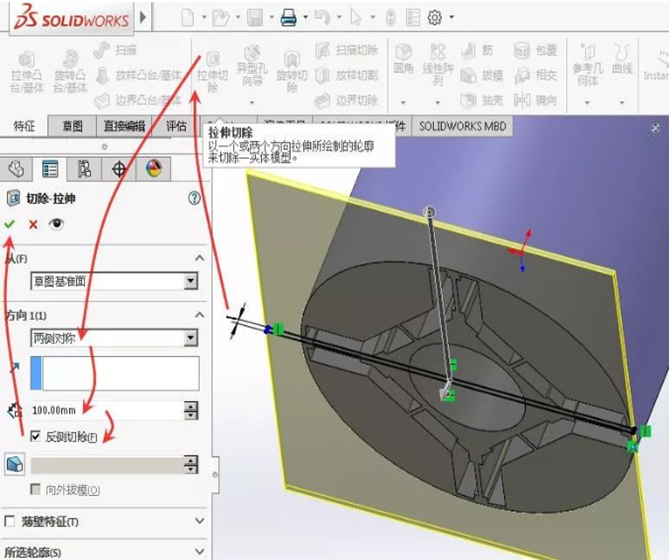
Using solid works software, cut the official case model of ANSYS to cut the complete rotor into 1mm axial length sheets. As shown in the figure.

In order to reduce iron loss, the rotor stamping for new energy vehicles is generally made of cold-rolled silicon steel with a thickness of about 0.3mm. After the punching plates are assembled into the rotor, the axial direction between the plates is generally fixed by means of self-adhesive, self-riveting, welding, etc., and properly relies on the glue in the magnetic steel groove. Since the axial force (electromagnetic unbalance force, external axial thrust, etc.) of the rotor punching plate can be basically ignored during operation, the 1mm sheet model can be simplified to represent the actual situation.

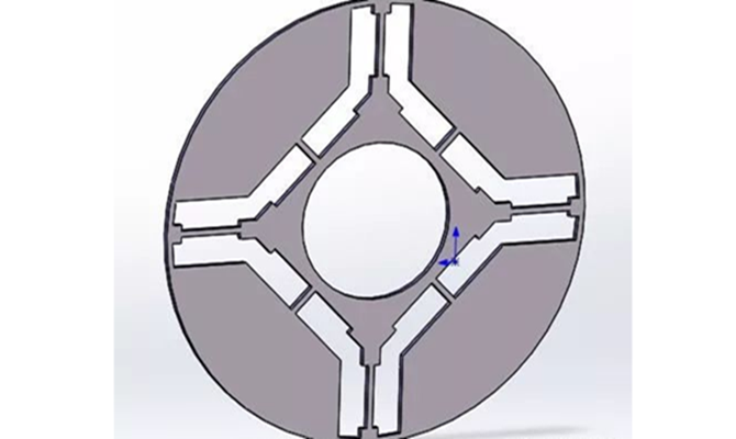
Because the magnetic steel and other models have not been retained when cutting into thin sheets, in order to facilitate the modification, the 360 ° circular punching model is cut into 1 / 8 sector parts with the help of Solid Works software. As shown in figure-5.
Similar to electromagnetic analysis, when calculating the strength, in order to save the amount of calculation, only the fan-shaped model of the minimum symmetrical region can be calculated. And properly add chamfer and draw magnetic steel model. For this paper, it is 1 / the 8 model.
Due to the existence of centrifugal force, the rotor punching plate is divided into four groups of approximately U-shaped outer rings and inner rings close to the rotating shaft by a radial magnetic bridge and axial magnetic bridge. These two types of magnetic isolation bridges mainly bear the centrifugal force caused by the outer ring U-shaped punch, magnetic steel, and magnetic steel glue.
Under certain conditions such as size, speed, and material, the smaller the area of the U-shaped area of the outer ring of the rotor magnetic steel, the smaller the total centrifugal force received at each magnetic isolation bridge. Relatively speaking, it is more conducive to high-speed operation.
During the actual performance development, we should fully communicate with the electromagnetic performance designers, select a more appropriate overall topology, and then carry out the detailed strength simulation design.
If the rotor adopts an enhanced heat transfer design such as oil cooling or air cooling, it shall also fully communicate with the heat dissipation performance designer to select a more comprehensive and reasonable comprehensive structure and performance.
For stress analysis, the key stress position is near the magnetic isolation bridge. The size and shape near the place shall be ensured in detail as far as possible without drastic changes, especially sharp right angles, and other shapes shall be avoided. Where the shape and section change significantly, such as the roots on both sides of the magnetic isolation bridge, complex curves, arcs, and other smooth transition forms shall be adopted to ensure the smooth and continuous transmission path of centrifugal force, so as to reduce the stress. When appropriate, various structural designs for stress relief and release shall also be adopted.
In addition, in order to avoid the sudden change of the force transmission path as far as possible, the shape transition from near the root of the magnetic isolation bridge should adopt the "convex" design as far as possible, such as outward chamfering, etc., and the "concave" design, such as slotting and opening, should be avoided as far as possible. Except for the design of stress relief holes specially used for stress relief.
More wonderful content will be shared in the next article. If you have any questions to discuss with BG motor engineers, please contact us!
 BACK
BACK

